Background
Little is understood about the propagation of radio waves in the area of 1800 - 2000 KHz. Although it is not situated far from the 80 metre band (3500 - 3800 KHz), its characteristics bear no resemblance. Attempts have been made to correlated a correlation between solar and geomagnetic Indices e.g sunspot numbers the K and A indices and the three hour k-index and these do not tie in with any form of prediction or indication that the band will open or yield good DX. When conditions are good on the 160 metre band it can sound like a good opening on the 20 metre band.
Signals on the 160 metre band are strongly affected by D-Layer absorption and consequently the propagation on this band is very much restricted to ground wave. During the night, however the density of the D-Layer reduces dramatically although it does not disappear - this will result in a corresponding reduction of signal absorption. Changes in the density of the D-Layer will therefore influence the absorption of the 160 metre signal in the night time hours.
Changes of electron density in the D-Layer will have profound effects on absorption levels during night time hours as, at lower frequencies, electron collisions with neutral ions occur more frequently than they do at higher frequencies. This is the major cause of absorption within the D-Layer. Another consideration is that frequencies in the 160 metre band are close to the electron gyro-frequency, generally between 700 and 1600 KHz. The gyro-frequency of an electron is a measure of the interaction between the electron in the earth's atmosphere and the earth's magnetic field. It is therefore obvious that the closer the carrier wave is to the gyro-frequency the more the energy is absorbed by the electron from that carrier wave.
During geomagnetic activity, such as that experienced following the occurrence of a solar flare, the orientation of the earth's magnetic field lines can change producing variations of signal strength. Auroral ovals, more prevalent after solar activity, can have an impact on radio wave propagation if the communication path lies within or along one. This will result in strong signal absorption and strong signal enhancements. Erratic signal behavior with strong and rapid signal fading may occur caused by multi-pathing, anomalous and rapid variations in absorption. This would be similar in effect to the rapid fading experienced on Radio Luxembourg and many other radio stations situated on the Medium Wave broadcast band.
Method to Determine Propagation on 160 Metres at Regular Intervals During the Day
In order to determine the day to day state of the 160 metre band at the EI5DD location in Galway, Weak Signal Propagation Reporting techniques were employed. This involves running a program developed by Joe Taylor K1JT on the computer and interfacing to the Yaesu FTDX5000MP via a Signalink USB data-modes interface. The power level was set to 5 watts output. The antenna in use was an inverted-L antenna with approximately 40ft in the vertical plane and 27 ft across the horizontal plane. The antenna was top loaded and was tuned by an SGC tuner at the bottom. The WSPR program allows periods in receive mode where signals way down in the noise floor are demodulated and once the information is received the results are uploaded to the WSPR reporting map on the
WSPR website. As all WSPR stations are linked to this site it is possible to see where those heard and those receiving signals are located.
Screenshot of the WSPR Program - Waterfall on the Left and Program Console/log on right
To the left, is the waterfall which shows the signals received in the form of white lines. The stronger the signal the heavier the line. To the right is the program console which show the log of stations received and the control section at the bottom. A transmission is made at approximately 8 minute intervals. Reception of signals is made at 2 minute intervals in between. The signals are all synchronised to a time reference to ensure that all systems on line transmit, receive and decode at accurately timed intervals.
Results
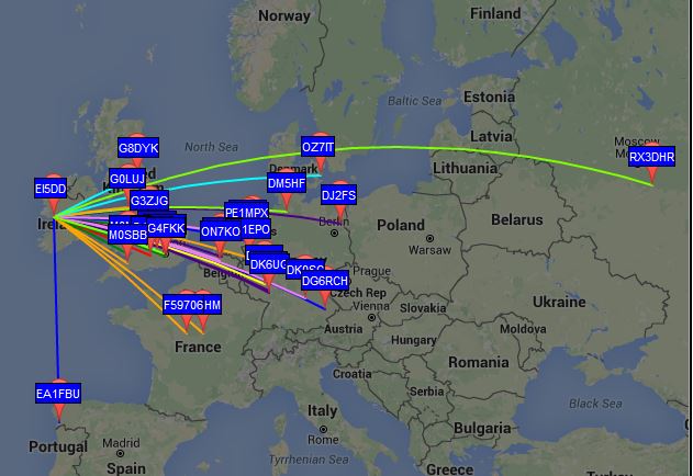
As can be seen on the WSPR Program console, signals rapidly decline as the graduation from night time to daytime occurs. Sunrise, on this occasion, was at 8)8 UTC and by 8:44 UTC the D-Layer as become sufficiently ionised to absorb all signals to the East of Galway and beyond ground wave paths. This ionisation will increase in density to solar noon. Beyond Solar the ionisation will slowly diminish. As the grey line transits towards Ireland, the D-Layer ionisation will diminish and signals will be heard once again from an easterly direction. Stations close to the transition from daylight to darkness will be heard first with more becoming apparent as the grey line transits towards Galway
The series of pictures below demonstrates the gradual increase in distance covered as the interface between night and day transits across Ireland and on up to midnight where the ionisation of the D-Layer is at a minimum.
The last of the series of pictures shows the total activity from 12 am to 7 am. Best DX is into Moscow. as the morning approaches so the ionisation of the D-Layer will gradually increase reducing the distance between stations both transmitting and receiving.
This experiment was continued over three days with no variation from the above apart from additional stations appearing or disappearing due to being taken off air or being switched on. No apparent DX opening has been found so far, but then these are probably few and far between. Interestingly, it has been noticed that there is no East - West propagation into the States as yet.
Operation to the States has been achieved from this location in the past so the path is possible. On one occasion there had been an opening to Australia showing up on the map but that was a one off and some years ago before a 24 hour watch was kept on the band.There are a number of WSPR stations transmitting over the 24 hour period and if an opening does occur it will be captured. A copy of Solar indices will be included and any other phenomena that may be relevant.
The beacon will be left running for another couple of weeks to see if anything stunning or startling should arise and hopefully one of the indices will correlate with an opening.
More to follow as and when it happens ............
References
- The 160-Meter Band: An Enigma Shrouded in Mystery - CARY OLER*, AND DR. THEODORE J. COHEN**, N4XX
Low Band DXing - John Devodere ON4UN


